

| Login | Join | KOREAN | X |
|
Digital Power Meter
|
Accura 3500E
|




| function | ||||
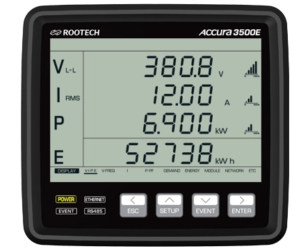
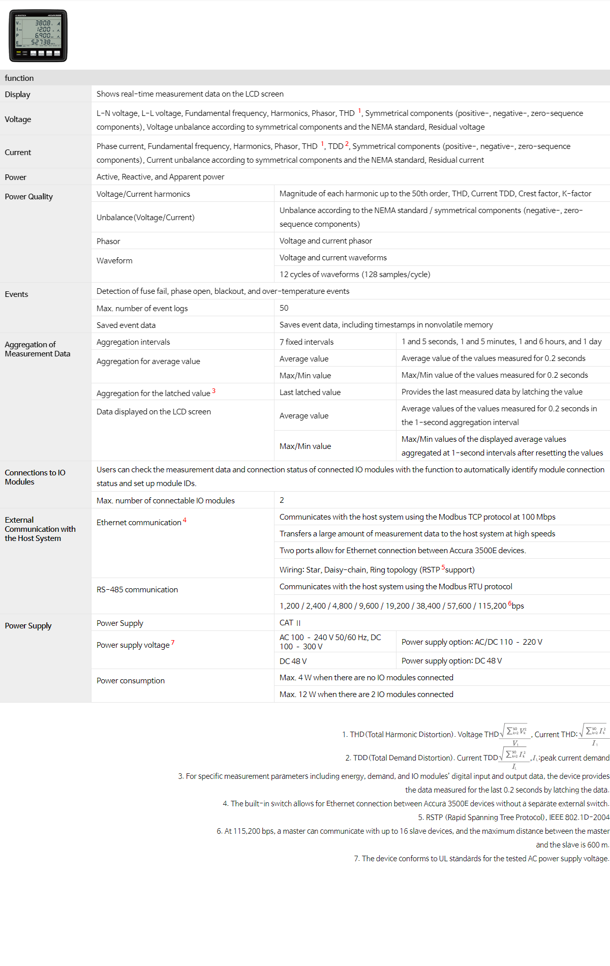
| Display | Shows real-time measurement data on the LCD screen | |||
| Voltage | L-N voltage, L-L voltage, Fundamental frequency, Harmonics, Phasor, THD 1, Symmetrical components (positive-, negative-, zero-sequence components), Voltage unbalance according to symmetrical components and the NEMA standard, Residual voltage | |||
| Current | Phase current, Fundamental frequency, Harmonics, Phasor, THD 1, TDD2, Symmetrical components (positive-, negative-, zero-sequence components), Current unbalance according to symmetrical components and the NEMA standard, Residual current | |||
| Power | Active, Reactive, and Apparent power | |||
|
Power Quality
|
Voltage/Current harmonics | Magnitude of each harmonic up to the 50th order, THD, Current TDD, Crest factor, K-factor | ||
| Unbalance(Voltage/Current) | Unbalance according to the NEMA standard / symmetrical components (negative-, zero-sequence components) | |||
| Phasor | Voltage and current phasor | |||
|
Waveform
|
Voltage and current waveforms | |||
| 12 cycles of waveforms (128 samples/cycle) | ||||
|
Events
|
Detection of fuse fail, phase open, blackout, and over-temperature events | |||
| Max. number of event logs | 50 | |||
| Saved event data | Saves event data, including timestamps in nonvolatile memory | |||
|
Aggregation of Measurement Data
|
Aggregation intervals | 7 fixed intervals | 1 and 5 seconds, 1 and 5 minutes, 1 and 6 hours, and 1 day | |
|
Aggregation for average value
|
Average value | Average value of the values measured for 0.2 seconds | ||
| Max/Min value | Max/Min value of the values measured for 0.2 seconds | |||
| Aggregation for the latched value3 | Last latched value | Provides the last measured data by latching the value | ||
|
Data displayed on the LCD screen
|
Average value | Average values of the values measured for 0.2 seconds in the 1-second aggregation interval | ||
| Max/Min value | Max/Min values of the displayed average values aggregated at 1-second intervals after resetting the values | |||
|
Connections to IO Modules
|
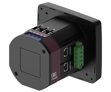
Users can check the measurement data and connection status of connected IO modules with the function to automatically identify module connection status and set up module IDs. | |||
| Max. number of connectable IO modules | 2 | |||
|
External Communication with
the Host System |
Ethernet communication4
|
Communicates with the host system using the Modbus TCP protocol at 100 Mbps | ||
| Transfers a large amount of measurement data to the host system at high speeds | ||||
| Two ports allow for Ethernet connection between Accura 3500E devices. | ||||
| Wiring: Star, Daisy-chain, Ring topology (RSTP5support) | ||||
|
RS-485 communication
|
Communicates with the host system using the Modbus RTU protocol | |||
| 1,200 / 2,400 / 4,800 / 9,600 / 19,200 / 38,400 / 57,600 / 115,2006bps | ||||
|
Power Supply
|
Installation category | CAT Ⅱ | ||
|
Power supply voltage7
|
AC 100 – 240 V 50/60 Hz, DC 100 – 300 V | Power supply option: AC/DC 110 – 220 V | ||
| DC 48 V | Power supply option: DC 48 V | |||
|
Power consumption
|
Max. 4 W when there are no IO modules connected | |||
| Max. 12 W when there are 2 IO modules connected | ||||
 , Current THD:
 ,
, :peak current demand
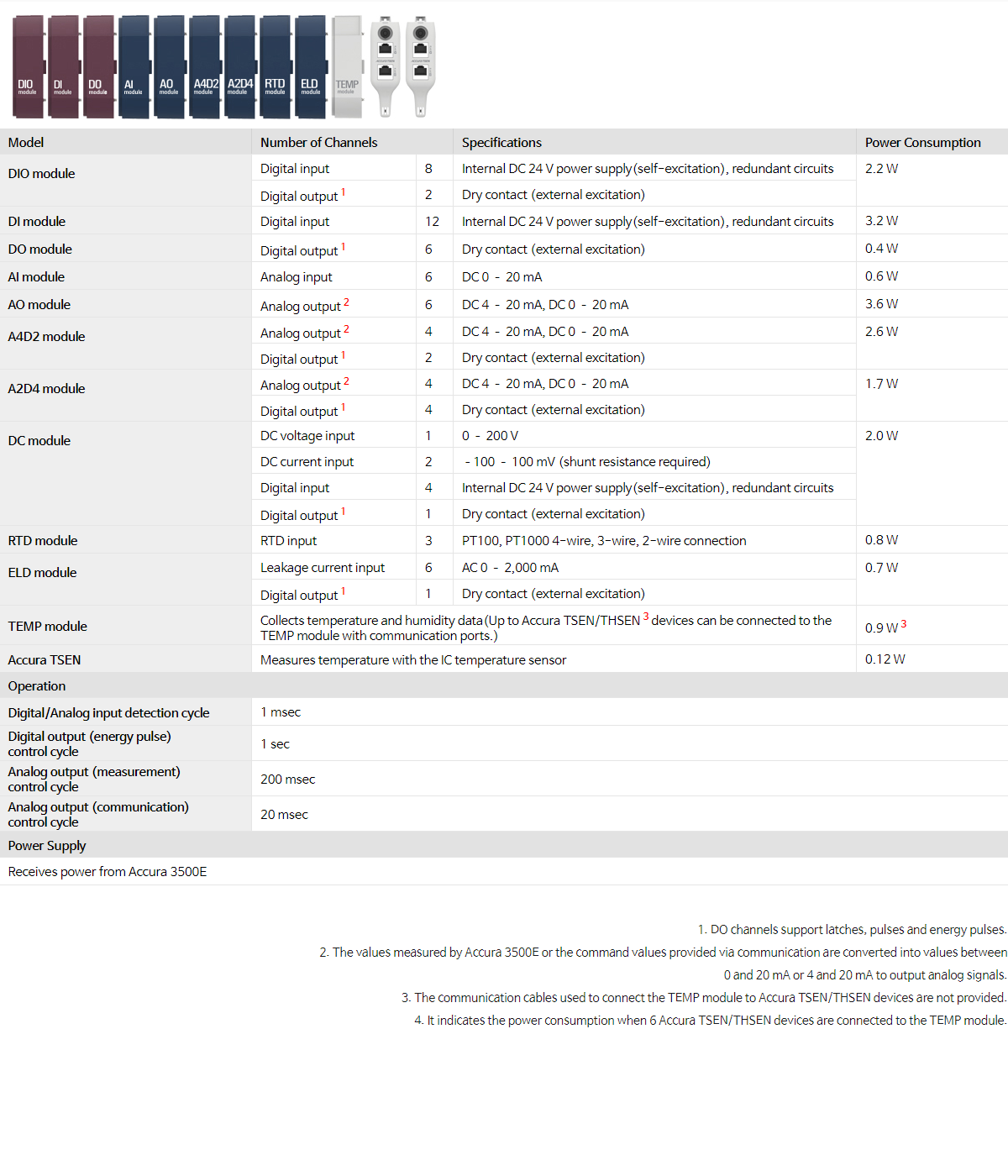

| Model | Number of Channels | Specifications | Power Consumption | |
|
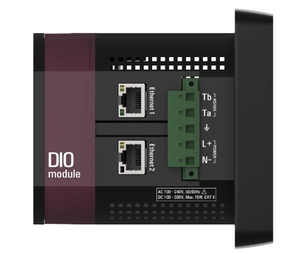
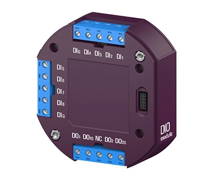
DIO module
|
Digital input | 8 | Internal DC 24 V power supply(self-excitation), redundant circuits | 2.2 W |
| Digital output1 | 2 | Dry contact (external excitation) | ||
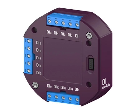
| DI module | Digital input | 12 | Internal DC 24 V power supply(self-excitation), redundant circuits | 3.2 W |
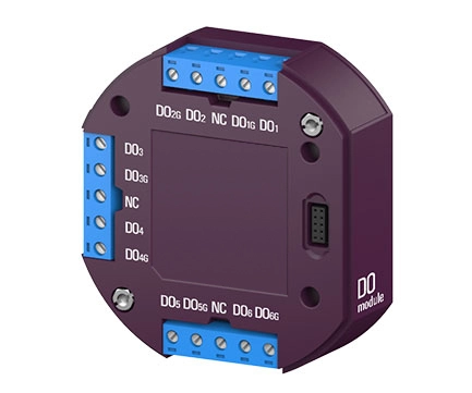
| DO module | Digital output1 | 6 | Dry contact (external excitation) | 0.4 W |
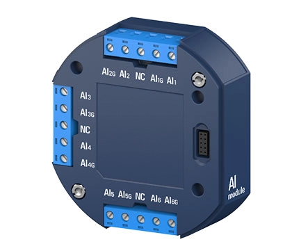
| AI module | Analog input | 6 | DC 0 – 20 mA | 0.6 W |
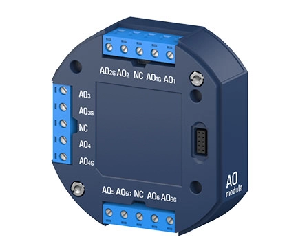
| AO module | Analog output2 | 6 | DC 4 – 20 mA, DC 0 – 20 mA | 3.6 W |
|
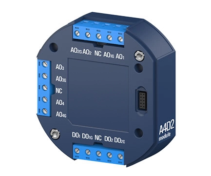
A4D2 module
|
Analog output2 | 4 | DC 4 – 20 mA, DC 0 – 20 mA | 2.6 W |
| Digital output1 | 2 | Dry contact (external excitation) | ||
|
A2D4 module
|
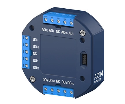
Analog output2 | 4 | DC 4 – 20 mA, DC 0 – 20 mA | 1.7 W |
| Digital output1 | 4 | Dry contact (external excitation) | ||
|
DC module
|
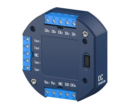
DC voltage input | 1 | 0 – 200 V | 2.0 W |
| DC current input | 2 | –100 – 100 mV (shunt resistance required) | ||
| Digital input | 4 | Internal DC 24 V power supply(self-excitation), redundant circuits | ||
| Digital output1 | 1 | Dry contact (external excitation) | ||
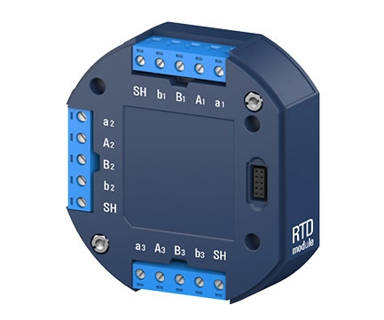
| RTD module | RTD input | 3 | PT100, PT1000 4-wire, 3-wire, 2-wire connection | 0.8 W |
|
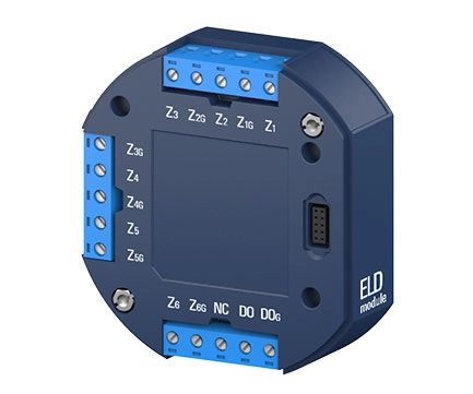
ELD module
|
Leakage current input | 6 | AC 0 – 2,000 mA | 0.7 W |
| Digital output1 | 1 | Dry contact (external excitation) | ||
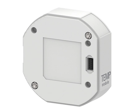
| TEMP module | Collects temperature and humidity data(Up to Accura TSEN/THSEN3 devices can be connected to the TEMP module with communication ports.) | 0.9 W3 | ||
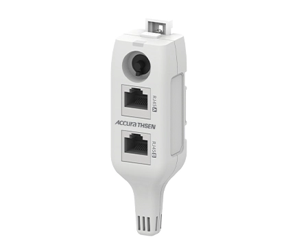
| Accura TSEN | Measures temperature with the IC temperature sensor | 0.12 W | ||
| Accura THSEN | Measures temperature and humidity with the IC temperature and humidity sensor | |||
| Operation | ||||
| Digital/Analog input detection cycle | 1 msec | |||
| Digital output (energy pulse) control cycle |
1 sec | |||
| Analog output (measurement) control cycle |
200 msec | |||
| Analog output (communication) control cycle |
20 msec | |||
| Power Supply | ||||
| Receives power from Accura 3500E | ||||


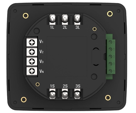
| Voltage Input | |||
| Port name | V1, V2, V3, VN | ||
| Connector type | Terminal block1 | ||
| Wire specification | 0.34 – 2.5 mm2 (22 – 14 AWG),copper | ||
| Wire temperature rating | Above 70°C | ||
| Measurement category | III | ||
| Withstand voltage | AC 3,000 V RMS, 60 Hz for 1 minute | ||
| mpedance | 10 MΩ/phase | ||
| Burden | 0.01 VA/phase @ 220 V | ||
| Wiring mode | 3P4W, 3P3W, 1P3W, 1P2W | ||
| Current Input | |||
| Port name | 1S, 2S, 3S on the power supply side, 1L, 2L, 3L ports on the load side (internal busbar) | ||
| Connector type | Terminal block2 | ||
| Wire specification | 2.5 – 6.0 mm2 (14 – 10 AWG), copper | ||
| Wire temperature rating | Above 70°C | ||
|
Rated current
|
5 A nominal/10 A full scale 3~ continuous | Accura 3500E-5A |
per UL 61010, 100 A for 1 second (thermal)
|
| 1 A nominal/2 A full scale 3~ continuous | Accura 3500E-1A | ||
| Burden | 0.01 VA/phase @10 A | ||
| Basic Measurement | |||
| Freq. measurement | Measuring range | 42 – 69 Hz | |
| Basic measurement | Measurement cycle | 0.2 sec (12 cycles @60 Hz, 10 cycles @50 Hz) | |
|
Voltage
|
Sampling | 512 samples/cycle | |
| Rated voltage (Un) | AC 230 V L–N | ||
|
Measuring range (accuracy guaranteed) |
AC 35 – 277 V L–N | ||
| AC 60 – 480 V L–L (for unearthed Delta & Y systems) | |||
| Accuracy | ±0.2 % Reading | IEC 61557-12 Class 0.2 | |
| Min. measured value | 5 V line–to–neutral | ||
|
Measurement data |
Line-to-neutral, Line-to-line voltage | ||
| Fundamental, Harmonics (up to the 50th order)3 | |||
| Phasor, THD | |||
| Symmetrical components (positive-, negative-, zero-sequence components) | |||
| Unbalance according to symmetrical components/the NEMA standard | |||
|
Residual voltage
|
Measuring method | Calculation of the sum of sampled three-phase L- N voltages | |
| Measurement data | RMS, Fundamental | ||
| Accuracy/operating range | ±0.2% Un4/Up to 277 V Line-to-neutral | ||
|
Current
|
Sampling | 256 samples/cycle | |
|
Measuring range(accuracy guaranteed) |
1 % In – 200 % In5 | Accura 3500E-5A | |
| 5 % In – 200 % In5 | Accura 3500E-1A | ||
| Accuracy | ±0.2 % Reading | IEC 61557-12 Class 0.2 | |
| Min. measured value | 0.1 % In5 | ||
|
Measurement data |
Phase current | ||
| Fundamental, Harmonics (up to the 50th order) | |||
| Phasor,THD, TDD | |||
| Symmetrical components(positive-, negative-, zero-sequence components) | |||
| Unbalance according to symmetrical components/the NEMA standard | |||
|
Residual current
|
Measuring method | Calculated by summing up sampled three-phase currents | |
| Measurement data | RMS, Fundamental | ||
| Accuracy/operating range | ±0.2% In/Up to 200 % of phase current In | ||
|
Power
|
Active power accuracy | IEC 61557–12 Class 0.5 | |
| Reactive power accuracy | IEC 61557–12 Class 1 | ||
| Apparent power accuracy | IEC 61557–12 Class 0.5 | ||
|
Energy
|
Active energy
|
Accuracy | IEC 62053–22 Class 0.5S |
| Type | Received, Delivered, Net, Sum (total) energy | ||
|
Reactive energy
|
Accuracy | IEC 62053–24 Class 0.5S | |
| Type | Energy in quadrant 1,2,3 and 4 | ||
| Apparent energy | Accuracy | IEC 61557–12 Class 0.5 | |
|
Demand
|
Current, Active power6 | Demand, Peak demand, Predicted demand7 | |
| Demand time setup | Demand time = Demand subinterval * the number of demand subintervals | ||
| Aggregation of Measurement Data | |||
| Aggregation intervals | 7 fixed intervals | 1 and 5 seconds, 1 and 5 minutes, 1 and 6 hours, and 1 day | |
|
Aggregation for
average value
|
Average value | Average value of the values measured for 0.2 seconds | |
| Max/Min value | Max/Min value of the values measured for 0.2 seconds | ||
| Aggregation for the latched value8 | Last latched value | Provides the last measured data by latching the value | |
|
Data displayed on the LCD screen
|
Average value | Average value on the values measured for 0.2 seconds (1-second aggregation interval) | |
| Max/Min value | Max/Min value of the average values for the 1-second aggregation interval after resetting the values | ||
| Power Quality | |||
|
Voltage/current harmonics
|
Harmonics order | Up to the 50th order | |
| Measurement data | Magnitude of each harmonic, voltage/current THD, current TDD, Crest factor, K-factor | ||
|
Voltage/current
unbalance
|
Measurement data
|
Unbalance according to the NEMA standard | |
| Negative-/zero-sequence unbalance according to symmetrical components | |||
| Phasor | Voltage/current | Phasor for the fundamental frequency | |
| Waveform | Voltage/current | 12 cycles of waveforms (128 samples/cycle) | |
| Events | |||
|
Measurement events
|
Type | Fuse fail, phase open, blackout, and over temperature events | |
| Event detection / time delay | Determined with the voltage/current data measured for 0.2 seconds (definite time: 1 second) | ||
| Saves 50 measurement events in nonvolatile memory | |||
|
System events
|
Events on module control, communication status, setup, etc. | ||
| Up to 1,000 system events can be saved in nonvolatile memory. | |||
| IO Module Control | |||
|
Module control
|
Max. number of connectable modules: 2 | ||
| Automatic detection of module status, module ID setup function | |||
| Collects data on measurement and status from connected IO modules | |||
| Display | |||
| LCD | FSTN, LED backlight | ||
| External Communication with the Host System | |||
|
Ethernet communication
|
Protocol | Modbus TCP protocol | |
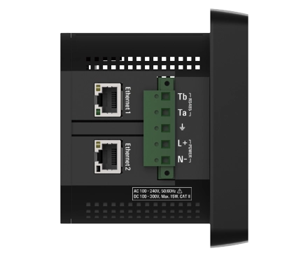
| Port | 2 ports, Ethernet switching9 | ||
| Connector type | RJ45 connector | ||
| Communication cable | protocol Cat 5e FTP, STP, SFTP10 | ||
| Cable length | Up to 100 m | ||
| Communication speed | 100 Base–TX (100 Mbps/Full Duplex) | ||
| Wiring mode | Star, daisy-chain, ring topology (RSTP11 support) | ||
| Max. number of connectable modules | 20 | ||
|
RS–485 communication
|
Protocol | Modbus RTU protocol | |
| Port | 1 port / Ta, Tb | ||
| Connector type | Screw-type terminal | ||
| Communication cable | UL 2919 RS–485 1P/2P 24 AWG | ||
| Cable length | Up to 1,219 m (4,000 ft) | ||
| Communication speed | 1,200– 115,200 bps12 | ||
| Max. number of connectable modules | 32 per bus12 | ||
| Power Supply | |||
| Port name | L+, N– | ||
| Connector type | Screw-type terminal (pluggable) | ||
| Wire specifications | 0.25– 4.0 mm2 (24 –12 AWG), copper | ||
| Wire temperature rating | Above 70 °C | ||
| Installation category | CAT Ⅱ | ||
| Operating environment | Pollution degree 2 | ||
| Withstand voltage | AC 3,000 V RMS, 60Hz for 1 minute | ||
|
Power consumption
|
Max. 4 W when there are no IO modules connected | ||
| Max. 12 W when there are 2 IO modules connected | |||
| Power Supply Option | AC/DC 110 - 220 V | DC 48 V | |
| Power supply voltage (Us)13 | AC 100 – 240 V 50/60 Hz, DC 100 – 300 V | DC 48 V | |
| Operating voltage range | 0.9 x Us ― 1.1 x Us | 0.75 x Us ― 1.3 x Us | |
|
Inrush current14
|
Peak 31 A, duration no more than 1 msec (AC 220 V) |
Peak 5 A, duration no more
than 200 μsec (DC 48 V)
|
|
| Peak 11 A, duration no more than 200 μsec (DC 110 V) | |||
| General | |||
| Weight | 500 g | ||
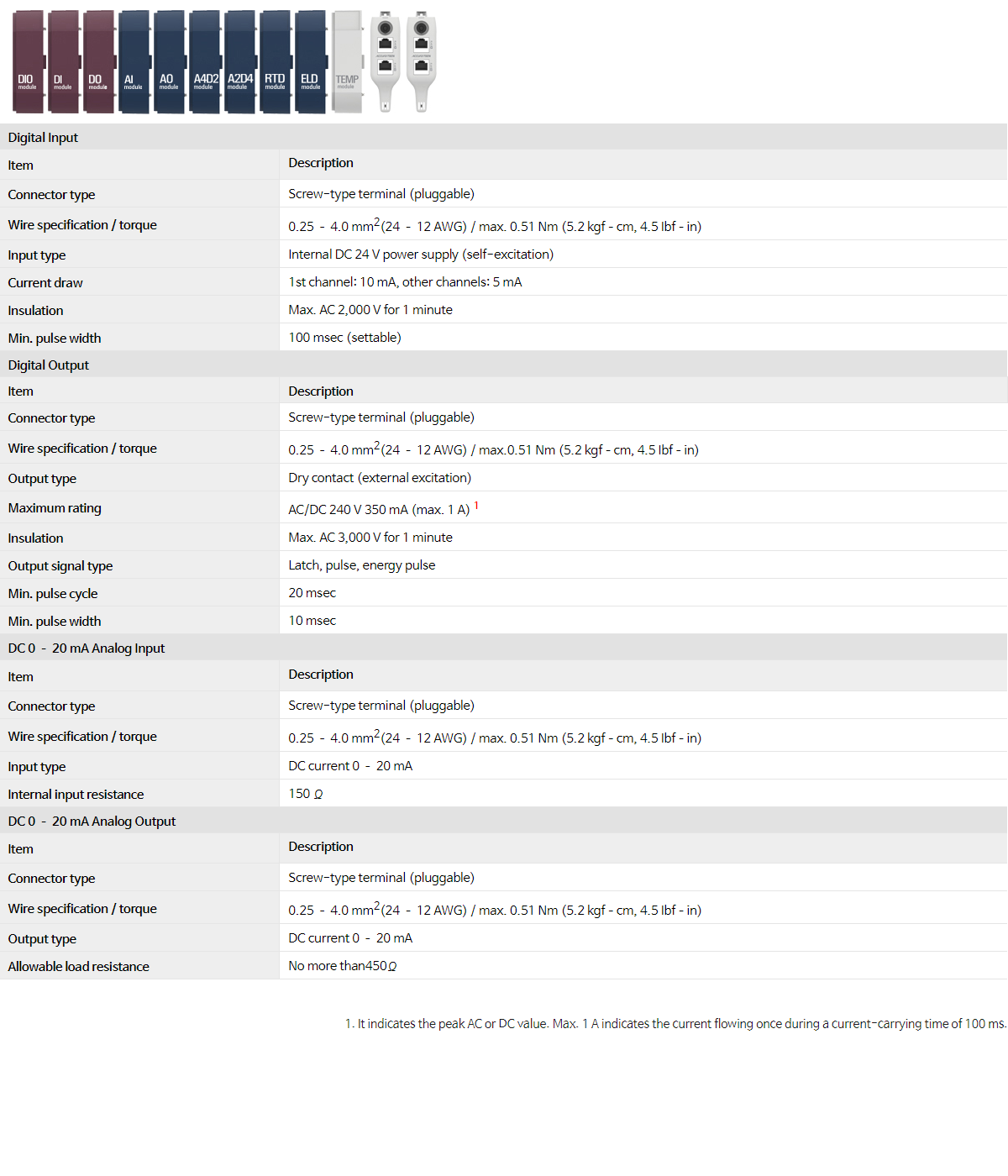

| Digital Input | |||
| Item | Description | ||
| Connector type | Screw-type terminal (pluggable) | ||
| Wire specification / torque | 0.25 – 4.0 mm2(24 – 12 AWG) / max. 0.51 Nm (5.2 kgf–cm, 4.5 Ibf–in) | ||
| Input type | Internal DC 24 V power supply (self-excitation) | ||
| Current draw | 1st channel: 10 mA, other channels: 5 mA | ||
| Insulation | Max. AC 2,000 V for 1 minute | ||
| Min. pulse width | 100 msec (settable) | ||
| Digital Output | |||
| Item | Description | ||
| Connector type | Screw-type terminal (pluggable) | ||
| Wire specification / torque | 0.25 – 4.0 mm2(24 – 12 AWG) / max.0.51 Nm (5.2 kgf–cm, 4.5 Ibf–in) | ||
| Output type | Dry contact (external excitation) | ||
| Maximum rating | AC/DC 240 V 350 mA (max. 1 A)1 | ||
| Insulation | Max. AC 3,000 V for 1 minute | ||
| Output signal type | Latch, pulse, energy pulse | ||
| Min. pulse cycle | 20 msec | ||
| Min. pulse width | 10 msec | ||
| DC 0 – 20 mA Analog Input | |||
| Item | Description | ||
| Connector type | Screw-type terminal (pluggable) | ||
| Wire specification / torque | 0.25 – 4.0 mm2(24 – 12 AWG) / max. 0.51 Nm (5.2 kgf–cm, 4.5 Ibf–in) | ||
| Input type | DC current 0 – 20 mA | ||
| Internal input resistance | 150 Ω | ||
| DC 0 – 20 mA Analog Output | |||
| Item | Description | ||
| Connector type | Screw-type terminal (pluggable) | ||
| Wire specification / torque | 0.25 – 4.0 mm2(24 – 12 AWG) / max. 0.51 Nm (5.2 kgf–cm, 4.5 Ibf–in) | ||
| Output type | DC current 0 – 20 mA | ||
| Allowable load resistance | No more than 450Ω | ||
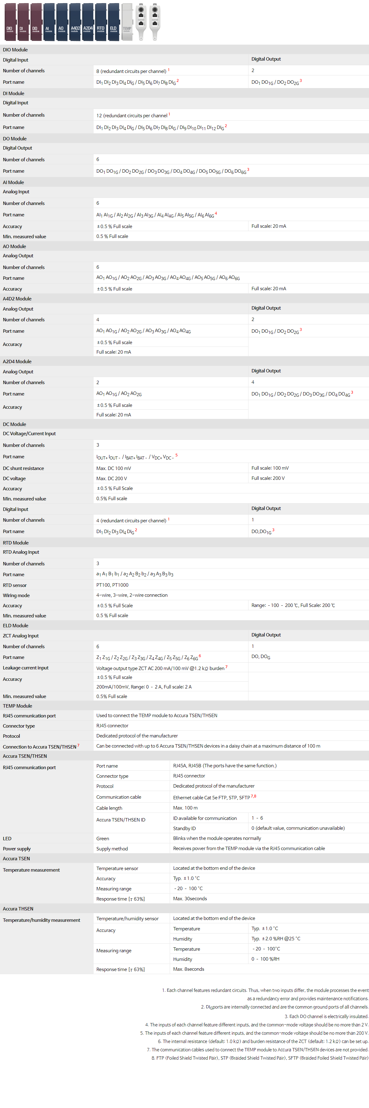

| DIO Module | ||||
| Digital Input | Digital Output | |||
| Number of channels | 8 (redundant circuits per channel)1 | 2 | ||
| Port name | DI1 DI2 DI3 DI4 DIG / DI5 DI6 DI7 DI8 DIG2 | DO1 DO1G / DO2 DO2G3 | ||
| DI Module | ||||
| Digital Input | ||||
| Number of channels | 12 (redundant circuits per channel1 | |||
| Port name | DI1 DI2 DI3 DI4 DIG / DI5 DI6 DI7 DI8 DIG / DI9 DI10 DI11 DI12 DIG2 | |||
| DO Module | ||||
| Digital Output | ||||
| Number of channels | 6 | |||
| Port name | DO1 DO1G / DO2 DO2G / DO3 DO3G / DO4 DO4G / DO5 DO5G / DO6 DO6G3 | |||
| AI Module | ||||
| Analog Input | ||||
| Number of channels | 6 | |||
| Port name | AI1 AI1G / AI2 AI2G / AI3 AI3G / AI4 AI4G / AI5 AI5G / AI6 AI6G4 | |||
| Accuracy | ±0.5 % Full scale | Full scale: 20 mA | ||
| Min. measured value | 0.5 % Full scale | |||
| AO Module | ||||
| Analog Output | ||||
| Number of channels | 6 | |||
| Port name | AO1 AO1G / AO2 AO2G / AO3 AO3G / AO4 AO4G / AO5 AO5G / AO6 AO6G | |||
| Accuracy | ±0.5 % Full scale | Full scale: 20 mA | ||
| A4D2 Module | ||||
| Analog Output | Digital Output | |||
| Number of channels | 4 | 2 | ||
| Port name | AO1 AO1G / AO2 AO2G / AO3 AO3G / AO4 AO4G | DO1 DO1G / DO2 DO2G3 | ||
Accuracy |
±0.5 % Full scale | |||
| Full scale: 20 mA | ||||
| A2D4 Module | ||||
| Analog Output | Digital Output | |||
| Number of channels | 2 | 4 | ||
| Port name | AO1 AO1G / AO2 AO2G | DO1 DO1G / DO2 DO2G / DO3 DO3G / DO4 DO4G3 | ||
Accuracy |
±0.5 % Full scale | |||
| Full scale: 20 mA | ||||
| DC Module | ||||
| DC Voltage/Current Input | ||||
| Number of channels | 3 | |||
| Port name | IOUT+ IOUT– / IBAT+ IBAT– / VDC+ VDC–5 | |||
| DC shunt resistance | Max. DC 100 mV | Full scale: 100 mV | ||
| DC voltage | Max. DC 200 V | Full scale: 200 V | ||
| Accuracy | ±0.5 % Full Scale | |||
| Min. measured value | 0.5% Full scale | |||
| Digital Input | Digital Output | |||
| Number of channels | 4 (redundant circuits per channel)1 | 1 | ||
| Port name | DI1 DI2 DI3 DI4 DIG2 | DO,DO1G3 | ||
| RTD Module | ||||
| RTD Analog Input | ||||
| Number of channels | 3 | |||
| Port name | a1 A1 B1 b1 / a2 A2 B2 b2 / a3 A3 B3 b3 | |||
| RTD sensor | PT100, PT1000 | |||
| Wiring mode | 4-wire, 3-wire, 2-wire connection | |||
| Accuracy | ±0.5 % Full Scale | Range: –100 – 200 ℃, Full Scale: 200 ℃ | ||
| Min. measured value | 0.5 % Full scale | |||
| ELD Module | ||||
| ZCT Analog Input | Digital Output | |||
| Number of channels | 6 | 1 | ||
| Port name | Z1 Z1G / Z2 Z2G / Z3 Z3G / Z4 Z4G / Z5 Z5G / Z6 Z6G6 | DO, DOG | ||
| Leakage current input | Voltage output type ZCT AC 200 mA/100 mV @1.2 kΩ burden7 | |||
Accuracy |
±0.5 % Full scale | |||
| 200mA/100mV, Range: 0 – 2 A, Full scale: 2 A | ||||
| Min. measured value | 0.5% Full scale | |||
| TEMP Module | ||||
| RJ45 communication port | Used to connect the TEMP module to Accura TSEN/THSEN | |||
| Connector type | RJ45 connector | |||
| Protocol | Dedicated protocol of the manufacturer | |||
| Connection to Accura TSEN/THSEN7 | Can be connected with up to 6 Accura TSEN/THSEN devices in a daisy chain at a maximum distance of 100 m | |||
| Accura TSEN/THSEN | ||||
|
RJ45 communication
port
|
Port name | RJ45A, RJ45B (The ports have the same function.) | ||
| Connector type | RJ45 connector | |||
| Protocol | Dedicated protocol of the manufacturer | |||
| Communication cable | Ethernet cable Cat 5e FTP, STP, SFTP7,8 | |||
| Cable length | Max. 100 m | |||
|
Accura TSEN/THSEN ID
|
ID available for communication | 1 – 6 | ||
| Standby ID | 0 (default value, communication unavailable) | |||
| LED | Green | Blinks when the module operates normally | ||
| Power supply | Supply method | Receives power from the TEMP module via the RJ45 communication cable | ||
| Accura TSEN | ||||
|
Temperature measurement
|
Temperature sensor | Located at the bottom end of the device | ||
| Accuracy | Typ. ±1.0 °C | |||
| Measuring range | –20 – 100 °C | |||
| Response time [τ 63%] | Max. 30seconds | |||
| Accura THSEN | ||||
|
Temperature/humidity
measurement
|
Temperature/humidity sensor | Located at the bottom end of the device | ||
|
Accuracy
|
Temperature | Typ. ±1.0 °C | ||
| Humidity | Typ. ±2.0 %RH @25 °C | |||
|
Measuring range
|
Temperature | –20 – 100°C | ||
| Humidity | 0 – 100 %RH | |||
| Response time [τ 63%] | Max. 8seconds | |||
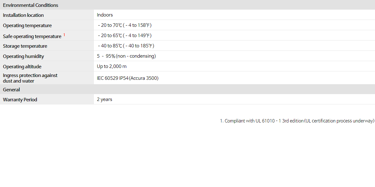
| Environmental Conditions | |||
| Installation location | Indoors | ||
| Operating temperature | –20 ― 70℃(–4 ― 158℉) | ||
| Operating environment | Pollution degree 2 | ||
| Safe operating temperature 1 | –20 ― 60℃(–4 ― 140℉) | ||
| Storage temperature | –40 ― 85℃(–40 ― 185℉) | ||
| Operating humidity | 5 ― 95%(non–condensing) | ||
| Operating altitude | Up to 2,000 m | ||
| Ingress protection against dust and water |
IEC 60529 IP54(Accura 3500E) | ||
| General | |||
| Warranty Period | 2 years | ||

|
|
102-611, 88, Sin won-ro, Yeongtong-gu, Suwon, Gyeonggi-do, Korea TEL 82 31 695 7350 FAX 82 31 695 7399 COPYRIGHT(C)ROOTECH. ALL RIGHTS RESERVED. |
|


