

| Login | Join | KOREAN | X |
|
Digital Power Meter
|
Accura 3500
|

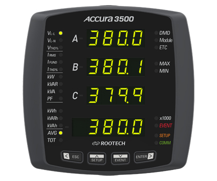
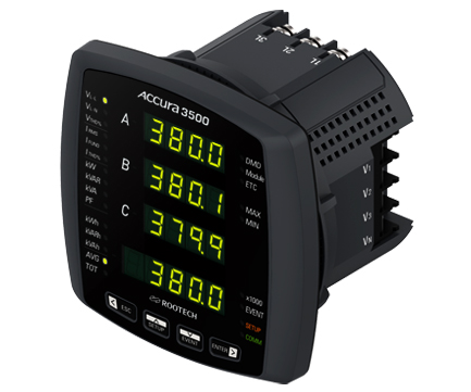
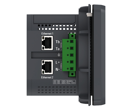
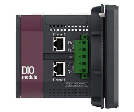


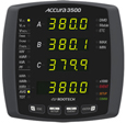
| Display | ||||
| Shows real–time measurement data on the FND display screen | ||||
| Voltage | ||||
| Line–to–neutral voltage, Line–to–line voltage, Fundamental frequency, Harmonics, Phasor diagram, THD1 | ||||
|
Symmetrical components(positive–, negative–, zero–sequence),Voltage unbalance based on symmetrical components, voltage unbalance according to the NEMA standard, Residual voltage |
||||
| Current | ||||
| Phase current, Fundamental frequency, Harmonics, Phasor diagram, THD1, TDD2 | ||||
| Symmetrical components(positive–, negative–, zero–sequence), Current unbalance based on symmetrical components, Current unbalance according to the NEMA standard, Residual current |
||||
| Power | ||||
| Active, Reactive, and Apparent power | ||||
| Power Quality | ||||
| Voltage / Current harmonics | Magnitude of each harmonic up to the 50th order, THD, Current TDD, Crest factor, K–factor | |||
| Unbalance(voltage/current) | Unbalance according to the NEMA standard, Negative–/zero–sequence unbalance based on symmetrical components | |||
| Phasor | Voltage and current phasor | |||
|
Waveform
|
Voltage and current waveforms | |||
| 12 cycles of waveforms(128 samples/cycle) | ||||
| Events | ||||
| Detection of fuse fail, phase open, blackout, and over-temperature events | ||||
| Max. number of event logs | 50 | |||
| Saved event data | Saves event data, including timestamps in nonvolatile memory | |||
| Aggregation of Measurement Data | ||||
| Aggregation intervals | 7 fixed intervals | 1 and 5 seconds, 1 and 5 minutes, 1 and 6 hours, and 1 day | ||
|
Aggregation for average value
|
Average value | Average value of the values measured for 0.2 seconds | ||
| Max/Min value | Max/Min value of the values measured for 0.2 seconds | |||
| Aggregation for the latched value1 | Last latched value | Provides the last measured data by latching the value | ||
|
Data displayed on the FND screen
|
Average value | Average values of the values measured for 0.2 seconds in the 1-second aggregation interval | ||
| Max/Min value | Max/Min values of the displayed average values aggregated at 1-second intervals after resetting the values | |||
| Connections of IO Modules | ||||
| Users can check the measurement data and connection status of the connected IO modules with the function to automatically detect module connection status and set up module IDs. | ||||
| Max. number of IO modules connectable to the back of the meter | 2 | |||
| External Communication with the Host System | ||||
|
Ethernet communication4
|
Communicates with the host system using the Modbus TCP protocol at 100 mbps | |||
| Transfers a large amount of measurement data to the host system at high speeds | ||||
| Two ports allow for Ethernet connection between Accura 3500 devices. | ||||
| Wiring: Star, Daisy–chain, Ring connections (RSTP support4) | ||||
|
RS-485 communication
|
Communicates with the host system using the Modbus RTU protocol | |||
| 1,200 / 2,400 / 4,800 / 9,600 / 19,200 / 38,400 / 57,600 / 115,2006 bps | ||||
| Power Supply | ||||
| Installation category | CAT Ⅱ | |||
| Power Consumption | ||||
|
Power supply voltage7
|
AC 100 — 240 V 50/60 Hz, DC 100 — 300 V | Power supply option:AC/DC 110 - 220 V | ||
| DC 48 V | Power supply option: DC 48 V | |||
|
Power consumption
|
Max. 4 W when there are no IO modules connected | |||
| Max. 12 W when there are 2 IO modules connected | ||||
 , Current THD:
  ,
, :fundamental voltage,
 :fundamental current
  ,
, :peak demand current

|
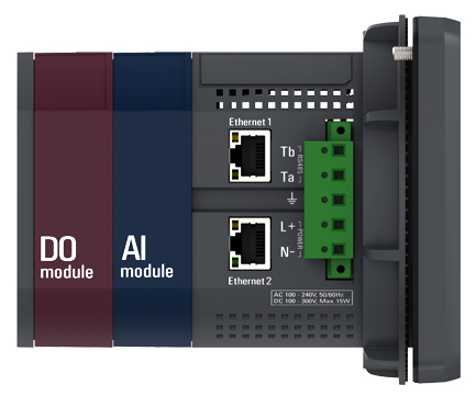
Accura 3500 comes with various IO modules that can be easily connected to the back of the device. Up to four modules can be attached regardless of connection sequence, and the same types of modules can be redundantly connected. |
||||
| Model | Number of Channels | Specifications | Power Consumption | |
|
DIO module
|
Digital input | 8 | Internal DC 24 V power supply(Self excitation), redundant circuits | 2.2 W |
| Digital output 1 | 2 | Dry contact (external excitation) | ||
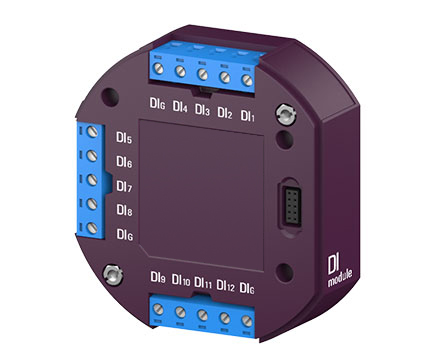
| DI module | Digital input | 12 | Internal DC 24 V power supply(self-excitation), redundant circuits | 3.2 W |
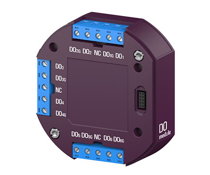
| DO module | Digital output 1 | 6 | Dry contact (external excitation) | 0.4 W |
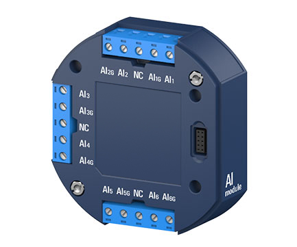
| AI module | Analog input | 6 | DC 0 – 20 mA | 0.6 W |
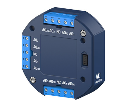
| AO module | Analog output2 | 6 | DC 0 – 20 mA | 3.6 W |
|
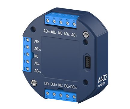
A4D2 module
|
Analog output2 | 4 | DC 0 – 20 mA | 2.6 W |
| Digital output 1 | 2 | Dry contact(external excitation) | ||
|
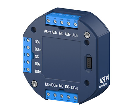
A2D4 module
|
Analog output2 | 4 | DC 0 – 20 mA | 1.7 W |
| Digital output 1 | 4 | Dry contact(external excitation) | ||
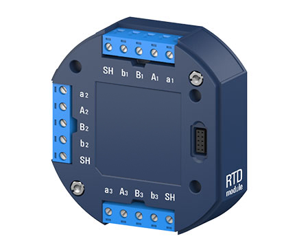
| RTD module | RTD input | 3 | PT100, PT1000 4–wire, 3–wire, 2–wire module | 0.8 W |
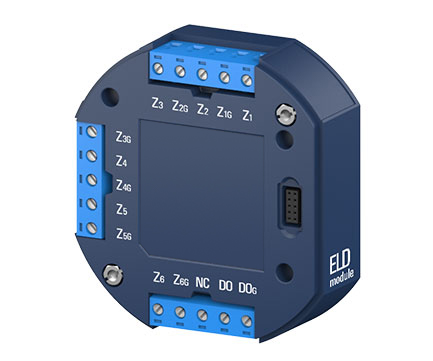
| ELD module | Leakage current input | 6 | AC 0 – 2,000 mA | 0.7 W |
| Digital output 1 | 1 | Dry contact(external excitation) | ||
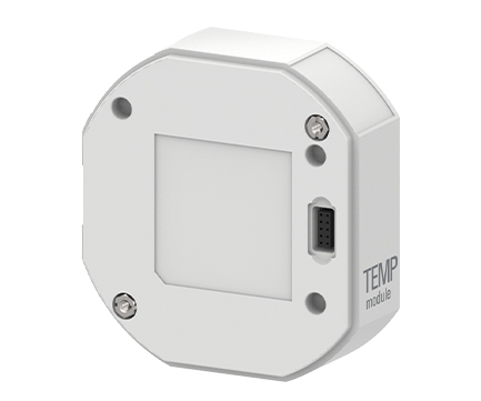
| TEMP module | Collects temperature and humidity data(Up to 6 Accura TSEN/THSEN3 devices can be connected to the TEMP module with communication ports.) | 0.9 W4 | ||
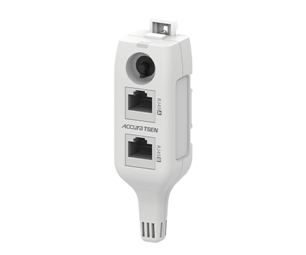
| Accura TSEN | Measures temperature with the IC temperature sensor | 0.12 W | ||
| Accura THSEN | Measures temperature and humidity with the IC temperature and humidity sensor | |||
| Operation | ||||
| Digital/Analog input detection cycle | 1 msec | |||
| Digital output (energy pulse) control cycle | 1 sec | |||
| Analog output (measurement) control cycle | 200 msec | |||
| Analog output (communication) control cycle | 20 msec | |||
| Power Supply | ||||
| Receives power from Accura 3500 | ||||


| Voltage Input | ||||
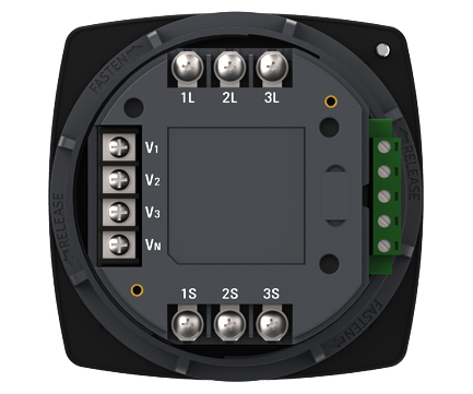
| Port name | V1, V2, V3, VN | |||
| Connector type | Terminal block1 | |||
| Wire specification | 0.34 — 2.5 mm2(22 — 14 AWG), copper | |||
| Wire temp rating | Above 70 ˚C | |||
| Measurement catagory | III | |||
| Withstand voltage | AC 3,000 V RMS, 60 Hz for 1 minute | |||
| Impedance | 10 MΩ/phase | |||
| Burden | 0.01 VA/phase @ 220 V | |||
| Wiring method | 3P4W, 3P3W, 1P3W, 1P2W | |||
| Current Input | ||||
| Port name | 1S, 2S, 3S ports on the power supply side, 1L, 2L, 3L ports on the load side(internal busbar) | |||
| Connector type | Terminal block2 | |||
| Wire specification | 2.5 — 6.0 mm2(14 — 10 AWG), copper | |||
| Wire temp rating | Above 70 ˚C | |||
|
Rated current |
5 A nominal/10 A full scale 3~ continuous | Accura 3500-5A | per UL 61010, 100 A for 1 second (thermal) | |
| 1 A nominal/2 A full scale 3~ continuous | Accura 3500-1A | |||
| Burden | 0.01 VA/phase @10 A | |||
| Basic Measurement | ||||
| Frequency measurement | Measuring range | 42 – 69 Hz | ||
| Basic measurement | Measurement cycle(gapless) | 0.2 sec(12 cycles @60 Hz, 10 cycles @50 Hz) | ||
|
Voltage
|
Sampling | 512 samples/cycle | ||
| Rated voltage (Un) | AC 230 V L–N | |||
|
Measuring range(accuracy guaranteed) |
35 — 277 V L–N | |||
| 60 — 480 V L–L (for unearthed Delta & Y systems) | ||||
| Accuracy | ±0.2 % Reading | IEC 61557-12 Class 0.2 | ||
| Min. measured value | 5 V Line–to–neutral(based on the secondary voltage of the PT when external PTs are connected) | |||
|
Measurement data |
Line-to-neutral, Line-to-line voltage | |||
| Fundamental, Harmonics(up to the 50th order)3 | ||||
| Phasor, THD | ||||
| Symmetrical components (positive-, negative-, zero-sequence components) | ||||
| Unbalance according to symmetrical components/ the NEMA standard | ||||
|
Residual voltage
|
Measuring method | Calculation of the sum of sampled three–phase line–to–neutral voltages | ||
| Measurement data | RMS, Fundamental | |||
| Accuracy / Operating range | ±0.2% Un4 / Up to 277 V Line–to–neutral | |||
|
Current
|
Sampling | 256 samples/cycle | ||
|
Measuring range (accuracy guaranteed) |
1 % In – 200 % In5 | Accura 3500-5A | ||
| 5 % In – 200 % In5 | Accura 3500-1A | |||
| Accuracy | ±0.2 % Reading | IEC 61557-12 Class 0.2 | ||
| Min. measured value | 0.1 % In5 | |||
|
Measurement data |
Phase current | |||
| Fundamental, Harmonics(up to the 50th order) | ||||
| Phasor, THD, TDD | ||||
| Symmetrical components (positive-, negative-, zero-sequence components) | ||||
| Unbalance according to symmetrical components/the NEMA standard | ||||
|
Residual current
|
Measuring method | Calculation of the sum of sampled three–phase currents | ||
| Measurement data | RMS, Fundamental | |||
| Accuracy / Operating range | ±0.2% In / Up to 200 % In of phase current | |||
|
Power
|
Accuracy of active power | IEC 61557–12 Class 0.5 | ||
| Accuracy of reactive power | IEC 61557–12 Class 1 | |||
| Accuracy of apparent power | IEC 61557–12 Class 0.5 | |||
|
Energy
|
Active
|
Accuracy | IEC 62053–22 Class 0.5S | |
| Type of energy | Received, Delivered, Net, Sum(total) energy | |||
|
Reactive
|
Accuracy | IEC 62053–24 Class 0.5S | ||
| Type of energy | Energy in quadrant 1, 2, 3 and 4 | |||
| Apparent | Accuracy | IEC 61557–12 Class 0.5 | ||
|
Demand
|
Current, Apparent power6 | Demand, Peak demand, Predicted demand7 | ||
| Demand time setup | Demand time = Demand sub–interval * the number of demand sub–intervals | |||
| Aggregation of Measurement Data | ||||
| Aggregation intervals | 7 fixed intervals | 1 and 5 seconds, 1 and 5 minutes, 1 and 6 hours, and 1 day | ||
|
Aggregation for average value
|
Average value | Average value of the values measured for 0.2 seconds | ||
| Max/Min value | Max/Min value of the values measured for 0.2 seconds | |||
| Aggregation for the latched value8 | Last latched value | Provides the last measured data by latching the value | ||
|
Data displayed on the FND screen
|
Average value | Average values of the values measured for 0.2 seconds in the 1-second aggregation interval | ||
| Max/Min value | Max/Min values of the displayed average values aggregated at 1-second intervals after resetting the values | |||
| Power Quality | ||||
|
Voltage/current harmonics
|
Harmonics order | Up to the 50th order | ||
| Measurement data | Magnitude of each harmonic, voltage/current THD, current TDD, Crest factor, K-factor | |||
|
Voltage/current
unbalance
|
Measurement data
|
Unbalance according to the NEMA standard | ||
| Negative-/zero sequence unbalance according to symmetrical components | ||||
| Phasor | Voltage/current | Phasor for the fundamental frequency | ||
| Waveform | Voltage/current | 12 cycles of waveforms (128 samples/cycle) | ||
| Events | ||||
|
Measurement events
|
Type | Fuse fail, phase open, blackout, and over temperature events | ||
| Event detection / time delay | Determined with the voltage/current data measured for 0.2 seconds (definite time: 1 second) | |||
| Saves 50 measurement events in nonvolatile memory | ||||
|
System events
|
Events on module control, communication status, setup, etc. | |||
| Up to 1,000 system events can be saved in nonvolatile memory. | ||||
| IO Module Control | ||||
|
Module control
|
Maximum number of connectable modules: 2 | |||
| Automatically detects the connection status of modules and performs the module ID setup function | ||||
| Collects measurement and status data from connected IO modules | ||||
| Display | ||||
|
FND
|
1st, 2nd, and 3rd rows | 4–digit 7–segment | ||
| 4th row | 5–digit 7–segment | |||
| External Communication with the Host System | ||||
|
Ethernet communication
|
Protocol | Modbus TCP protocol | ||
| Port | 2 ports, Ethernet switching9 | |||
| Connector type | RJ45 connector | |||
| Communication cable | Ethernet cable Cat 5e FTP, STP, SFTP10 | |||
| Cable length | Up to 100 m | |||
| Communication speed | 100 Base–TX(100 Mbps/Full Duplex) | |||
| Wiring mode | Star, daisy chain, ring topology(RSTP11support) | |||
| Max. number of connectable modules | 20 | |||
|
RS–485 communication
|
Protocol | Modbus RTU protocol | ||
| Port | 1 port/Ta, Tb | |||
| Connector type | Screw-type terminal | |||
| Communication cable | UL 2919 RS–485 1P/2P 24 AWG | |||
| Cable length | Up to 1,219 m (4,000 ft) | |||
| Communication speed | 1,200 / 2,400 / 4,800 / 9,600 / 19,200 / 38,400 / 57,600 / 115,200 bps12 | |||
| Max. number of connectable modules | 32 per bus12 | |||
| Power Supply | ||||
| Port name | L+, N– | |||
| Connector type | Screw-type terminal (pluggable) | |||
| Wire specifications | 0.25— 4.0 mm2 (24 —12 AWG), copper | |||
| Wire temperature rating | Above 70 °C | |||
| Installation category | CAT II | |||
| Operating environment | Pollution degree 2 | |||
| Withstand voltage | AC 3,000 V RMS, 60 Hz for 1 minute | |||
|
Power consumption
|
Max. 4 W when there are no IO modules connected | |||
| Max. 12 W when there are 2 IO modules connected | ||||
| Power Supply Option | AC/DC 110 - 220 V | DC 48 V | ||
| Power supply voltage (Us)13 | AC 100 — 240 V 50/60 Hz, DC 100 — 300 V | DC 48 V | ||
| Operating voltage range | 0.9 x Us – 1.1 x Us | 0.75 x Us ― 1.3 x Us | ||
|
Inrush current14
|
Peak 31 A, duration no more than 1 msec (AC 220 V) |
Peak 5 A, duration no more than 200 μsec (DC 48 V)
|
||
| Peak 11 A, duration no more than 200 μsec (DC 110 V) | ||||
| General | ||||
| Weight | 500 g | |||


| Digital Input | |||
| Item | Description | ||
| Connector type | Screw–type terminal(Pluggable) | ||
| Wire specification | 0.25 — 4.0 mm2 (24 — 12 AWG),max 0.51 Nm (5 kgf–cm, 4.5 Ibf–in) | ||
| Input type | Internal DC 24 V power supply(self–excitation) | ||
| Carried current | 1st channel : 10 mA, other channels: 5 mA | ||
| Insulation | Max. AC 2,000 V for 1 minute | ||
| Minimum pulse width | 100 msec(settable) | ||
| Digital Output | |||
| Item | Description | ||
| Connector type | Screw–type terminal (Pluggable) | ||
| Wire specification | 0.25 — 4.0 mm2 (24 — 12 AWG), max 0.51 Nm (5.2 kgf–cm, 4.5 Ibf–in) | ||
| Output type | Dry contact(external excitation) | ||
| Maximum Rating | AC/DC 240 V 350 mA (max. 1 A)1 | ||
| Insulation | Max. AC 3,000 V for 1 minute | ||
| Output signal type | Latch, pulse, energy pulse | ||
| Minimum pulse cycle | 20 msec | ||
| Minimum pulse width | 10 msec | ||
| DC 0–20mA Analog Input | |||
| Item | Description | ||
| Connector type | Screw–type terminal(Pluggable) | ||
| Wire specification | 0.25 — 4.0 mm2 (24 — 12 AWG), max 0.51 Nm (5.2 kgf–cm, 4.5 Ibf–in) | ||
| Input type | DC current 0 – 20 mA | ||
| Internal input resistance | 150 Ω | ||
| DC 0–20mA Analog Output | |||
| Item | Description | ||
| Connector type | Screw–type terminal (pluggable) | ||
| Wire specification | 0.25 — 4.0 mm2 (24— 12 AWG), max 0.51 Nm (5.2 kgf–cm, 4.5 Ibf–in) | ||
| Output type | DC Current 0 – 20 mA | ||
| Allowable load resistance | No more than 450 Ω | ||


| DIO Module | ||||
| Digital Input | Digital Output | |||
| Number of channels | 8 (redundant circuits per channel)1 | 2 | ||
| Port name | DI1 DI2 DI3 DI4 DIG / DI5 DI6 DI7 DI8 DIG2 | DO1 DO1G / DO2 DO2G3 | ||
| DI Module | ||||
| Digital Input | ||||
| Number of channels | 12 (redundant circuits per channel)1 | |||
| Port name | DI1 DI2 DI3 DI4 DIG / DI5 DI6 DI7 DI8 DIG / DI9 DI10 DI11 DI12 DIG2 | |||
| DO Module | ||||
| Digital Output | ||||
| Number of channels | 6 | |||
| Port name | DO1 DO1G / DO2 DO2G / DO3 DO3G / DO4 DO4G / DO5 DO5G / DO6 DO6G3 | |||
| AI Module | ||||
| Analog Input | ||||
| Number of channels | 6 | |||
| Port name | AI1 AI1G / AI2 AI2G / AI3 AI3G / AI4 AI4G / AI5 AI5G / AI6 AI6G4 | |||
| Accuracy | ±0.5 % Full scale | Full scale : 20 mA | ||
| Min. measured value | 0.5 % Full scale | |||
| AO Module | ||||
| Analog Output | ||||
| Number of channels | 6 | |||
| Port name | AO1 AO1G / AO2 AO2G / AO3 AO3G / AO4 AO4G / AO5 AO5G / AO6 AO6G | |||
| Accuracy | ±0.5 % Full scale | Full scale : 20 mA | ||
| A4D2 Module | ||||
| Analog Output | Digital Output | |||
| Number of channels | 4 | 2 | ||
| Port name | AO1 AO1G / AO2 AO2G / AO3 AO3G / AO4 AO4G | DO1 DO1G / DO2 DO2G3 | ||
| Accuracy | ±0.5 % Full scale | Full scale : 20 mA | – | |
| A2D4 Module | ||||
| Analog Output | Digital Output | |||
| Number of channels | 2 | 4 | ||
| Port name | AO1 AO1G / AO2 AO2G | DO1 DO1G / DO2 DO2G / DO3 DO3G / DO4 DO4G3 | ||
| Accuracy | ±0.5 % Full scale | Full scale : 20 mA | – | |
| RTD Module | ||||
| RTD Analog Input | ||||
| Number of channels | 3 | |||
| Port name | a1 A1 B1 b1 / a2 A2 B2 b2 / a3 A3 B3 b3 | |||
| RTD sensor | PT100, PT1000 | |||
| Wiring mode | 4-wire, 3-wire, 2-wire connection | |||
| Accuracy | ±0.5 % Full Scale | Range: –100 – 200 °C, Full Scale: 200 °C | ||
| Min. measured value | 0.5 % Full scale | |||
| ELD Module | ||||
| ZCT Analog Input | Digital Output | |||
| Number of channels | 6 | 1 | ||
| Port name | Z1 Z1G / Z2 Z2G / Z3 Z3G / Z4 Z4G / Z5 Z5G / Z6 Z6G4 | DO, DOG | ||
| Leakage current input | Voltage output type ZCT AC 200 mA/100 mV @1.2 kΩ burden5 | |||
| Accuracy | ±0.5 % Full Scale | 200 mA/100 mV, Range: 0 – 2 A, Full Scale: 2 A | ||
| Min. measured value | 0.5 % Full scale | |||
| TEMP Module | ||||
| RJ45 communication port | Used to connect the TEMP module to Accura TSEN/THSEN | |||
| Connector type | RJ45 connector | |||
| Protocol | Dedicated protocol of the manufacturer | |||
| Connection with Accura TSEN/THSEN6 | Can be connected with up to 6 Accura TSEN/THSEN devices in a daisy chain at a maximum distance of 100 m. | |||
| Accura TSEN/THSEN | ||||
|
RJ45 communication port
|
Port name | RJ45A, RJ45B(The ports have the same function.) | ||
| Connector type | RJ45 connector | |||
| Protocol | Dedicated protocol of the manufacturer | |||
| Communication cable | Ethernet cable Cat 5e FTP, STP, SFTP7 | |||
| Cable length | Max. 100 m | |||
|
Accura TSEN/THSEN ID
|
ID available for communication | 1 – 6 | ||
| Standby ID | 0 (default value, communication unavailable) | |||
| LED | Green | Blinks when the module operates normally | ||
| Power supply | Supply method | Receives power from the TEMP module via the RJ45 communication cable | ||
| Accura TSEN | ||||
|
Temperature measurement
|
Temperature sensor | Located at the bottom end of the device | ||
| Accuracy | Typ. ±1.0 °C | |||
| Measuring range | –20 – 100 °C | |||
| Response time [τ 63%] | Max. 30 seconds | |||
| Accura THSEN | ||||
|
Temperature/humidity
measurement
|
Temperature/humidity sensor | Located at the bottom end of the device | ||
|
Accuracy
|
Temperature | Typ. ±1.0 °C | ||
| Humidity | Typ. ±2.0 %RH @°C | |||
|
Measuring range
|
Temperature | -20 — 100°C | ||
| Humidity | 0 — 100 %RH | |||
| Response time [τ 63%] | Max. 8 seconds | |||

| Environmental Conditions | |||
| Installation location | Indoors | ||
| Operating temperature | –20 — 70℃(–4 — 158℉) | ||
| Safe operating temperature 1 | –20 — 60℃(–4 — 140℉) | ||
| Storage temperature | –40 — 85℃(–40 — 185℉) | ||
| Operating humidity | 5 — 95%(non–condensing) | ||
| Operating altitude | Up to 2,000 m | ||
| Ingress protection against dust and water |
IEC 60529 IP54(Accura 3500) | ||
| General | |||
| Warranty Period | 2 years | ||

|
|
102-611, 88, Sin won-ro, Yeongtong-gu, Suwon, Gyeonggi-do, Korea TEL 82 31 695 7350 FAX 82 31 695 7399 COPYRIGHT(C)ROOTECH. ALL RIGHTS RESERVED. |
|


