| Protection Relays |
| Frequency |
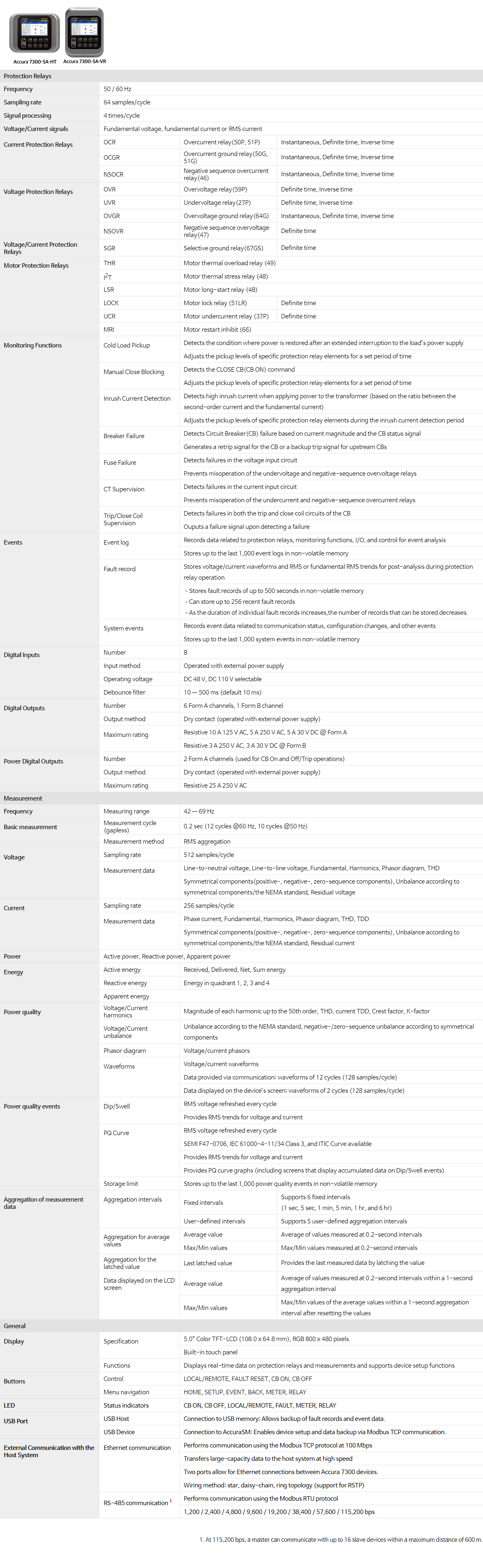
50/60 Hz |
| Sampling rate |
64 samples/cycle |
| Signal processing |
4 times/cycle |
| Voltage/Current signals |
Fundamental voltage, fundamental current or RMS current |
|
Current Protection Relays
|
OCR |
Overcurrent relay(50P, 51P) |
Instantaneous, Definite time, Inverse time |
| OCGR |
Overcurrent ground relay(50G, 51G) |
Instantaneous, Definite time, Inverse time |
| NSOCR |
Negative-sequence overcurrent relay(46) |
Instantaneous, Definite time, Inverse time |
|
Voltage Protection Relays
|
OVR |
Overvoltage relay(59P) |
Definite time, Inverse time |
| UVR |
Undervoltage relay(27P) |
Definite time, Inverse time |
| OVGR |
Overvoltage ground relay(64G) |
Instantaneous, Definite time, Inverse time |
| NSOVR |
Negative-sequence overvoltage relay(47) |
Definite time |
| Voltage/Current
Protection Relays |
SGR |
Selective ground relay(67GS) |
Definite time |
|
Motor Protection Relays
|
THR |
Motor thermal overload relay (49) |
| I2t |
Motor thermal stress relay (48) |
| LSR |
Motor long-start relay (48) |
| Lock |
Motor lock relay (51LR) |
Definite time |
| UCR |
Motor undercurrent relay (37P) |
Definite time |
| MRI |
Motor restart inhibit (66) |
|
Supervision Functions
|
Cold Load Pickup
|
Detects the condition where power is restored after an extended interruption to the
load’s power supply |
| Adjusts the pickup levels of specific protection relay elements over a set period |
|
Manual Close Blocking
|
Detects the CLOSE CB (CB ON) command |
| Adjusts the pickup levels of specific protection relay elements over a set period |
|
Inrush Current Detection
|
Detects high inrush current when applying power to the transformer
(based on the ratio of the second-order current to the fundamental current) |
| Adjusts the pickup levels of specific protection relay elements during the inrush current
detection period |
|
Breaker Failure
|
Detects Circuit Breaker(CB) failure based on current magnitude and the CB status signal |
| Generates a retrip signal for the CB or a backup trip signal for upstream CBs |
|
Fuse Failure
|
Detects failures in the voltage input circuit |
| Prevents misoperation of the undervoltage and negative-sequence overvoltage relays |
|
CT Supervision
|
Detects failures in the current input circuit |
| Prevents misoperation of the undercurrent and negative-sequence overcurrent relays |
|
Trip/Close Coil Supervision
|
Detects failures in both the trip and close coil circuits of the CB |
| Outputs a failure signal upon detecting a failure |
|
Events
|
Event log
|
Records data related to protection relays, monitoring functions, I/O, and control
for event analysis |
| Stores up to the last 1,000 event logs in non-volatile memory |
|
Fault record
|
Stores voltage/current waveforms and RMS or fundamental RMS trends for post-analysis during protection relay operation |
–Stores fault records of up to 500 seconds in non-volatile memory
–Can store up to 256 recent fault records
–As the duration of individual fault records increases, the number of records that can be stored decreases. |
|
System event
|
Records event data related to communication status, configuration changes, and other events |
| Stores up to the last 1,000 system events in non-volatile memory |
|
Digital Inputs
|
Number of channels |
8 |
| Input method |
Operated with an external power supply |
| Operating voltage |
DC 48 V, DC 110 V selectable |
| Debounce filter |
10 — 500 ms (default 10 ms) |
|
Digital Outputs
|
Number of channels |
6 (Form A), 1 (Form B) |
| Output method |
Dry contacts (operated with an external power supply) |
|
Maximum rating
|
Resistive 10 A 125 V AC, 5 A 250 V AC, 5 A 30 V DC @ Form A |
| Resistive 3 A 250 V AC, 3 A 30 V DC @ Form B |
|
Power Digital Outputs
|
Number of channels |
2 Form A channels (used for CB On, Off, and Trip operations) |
| Output method |
Dry contacts (operated with an external power supply) |
| Maximum rating |
Resistive 25 A 250 V AC |
| Measurement |
| Frequency |
Measuring range |
42 — 69 Hz |
|
Basic measurement |
Measurement cycle (gapless) |
0.2 sec (12 cycles @60 Hz, 10 cycles @50 Hz) |
| Measurement method |
RMS aggregation |
|
Voltage
|
Sampling rate |
512 samples/cycle |
|
Measurement data
|
Line-to-neutral voltage, Line-to-line voltage, Fundamental, Harmonics,
Phasor diagram, THD |
| Symmetrical components (positive-, negative-, zero-sequence components),
Unbalance based on symmetrical components or the NEMA standard, Residual voltage |
|
Current
|
Sampling rate |
256 samples/cycle |
|
Measurement data
|
Phase current, Fundamental, Harmonics, Phasor diagram, THD, TDD |
| Symmetrical components (positive-, negative-, zero-sequence components),
Unbalance based on symmetrical components or the NEMA standard, Residual current |
| Power |
Active power, Reactive power, Apparent power |
|
Energy
|
Active energy |
Received, Delivered, Net, Sum energy |
| Reactive energy |
Energy in quadrants 1, 2, 3 and 4 |
| Apparent energy |
|
Power quality
|
Voltage/Current harmonics |
Magnitude of each harmonic up to the 50th order, THD, current TDD, Crest factor, K-factor |
| Voltage/Current unbalance |
Unbalance based on the NEMA standard, negative-/zero-sequence unbalance based on
symmetrical components |
| Phasor diagram |
Voltage/current phasors |
|
Waveforms
|
Voltage/current waveforms |
| Data provided via communication: 12-cycle waveforms (128 samples/cycle) |
| Data displayed on the device’s screen: 2-cycle waveforms (128 samples/cycle) |
|
Power quality events
|
Dip/Swell
|
Measures RMS voltage, updated every cycle |
| Provides RMS trends for voltage and current |
|
PQ Curve
|
Measures RMS voltage, updated every cycle |
| Supports SEMI F47-0706, IEC 61000-4-11/34 Class 3, and ITIC Curve |
| Provides RMS trends for voltage and current |
| Provides PQ curve graphs (including screens that display accumulated data on Dip/Swell events) |
| Storage limit |
Stores up to the last 1,000 power quality events in non-volatile memory |
|
Aggregation of measurement data
|
Aggregation intervals
|
Fixed intervals
|
Supports 6 fixed intervals
(1 sec, 5 sec, 1 min, 5 min, 1 hr, and 6 hrs) |
| User-defined intervals |
Supports 5 user-defined aggregation intervals |
|
Aggregation for average values
|
Average value |
Average of values measured at 0.2-second intervals |
| Max/Min values |
Maximum and minimum values measured at 0.2-second
intervals |
| Aggregation for the latched value |
Last latched value |
Provides the last measured data by latching the value |
|
Data displayed on the LCD screen
|
Average value
|
Average of values measured at 0.2-second intervals
over a 1-second aggregation period |
Max/Min values
|
Maximum and minimum values of the average values over a
1-second aggregation period after resetting the values |
| General |
|
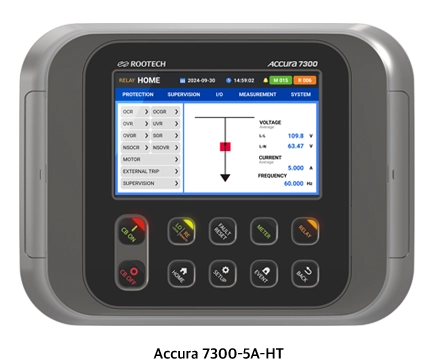
Display
|
Specifications
|
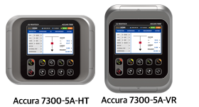
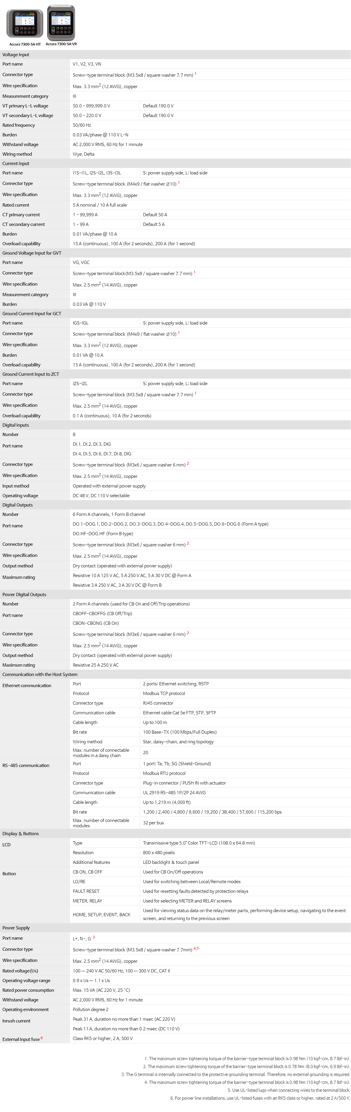
5.0” Color TFT-LCD (108.0 x 64.8 mm), RGB 800 x 480 pixels |
| Built-in touch panel |
| Functions |
Displays real-time data on protection relays and measurements and supports
device setup |
|
Buttons
|
Control |
LOCAL/REMOTE, FAULT RESET, CB ON, CB OFF |
| Menu navigation |
HOME, SETUP, EVENT, BACK, METER, RELAY |
| LED |
Status indicators |
CB ON, CB OFF, LOCAL/REMOTE, FAULT, METER, RELAY |
|
USB Port
|
USB Host |
Connection to USB memory: Enables backup of fault records and event data. |
| USB Device |
Connection to AccuraSM: Supports device setup and data backup through Modbus
TCP communication. |
|
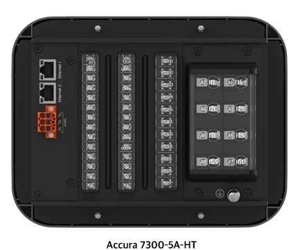
External communication with the host system
|
Ethernet communication
|
Performs communication using the Modbus TCP protocol at 100 Mbps |
| Transfers large-capacity data to the host system at high speed |
| Two ports enable Ethernet connections between Accura 7300 devices. |
| Wiring methods: star, daisy-chain, ring topology (supports RSTP) |
|
RS-485 communication1
|
Performs communication using the Modbus RTU protocol |
| 1,200 / 2,400 / 4,800 / 9,600 / 19,200 / 38,400 / 57,600 / 115,200 bps |
1. At 115,200 bps, a master can communicate with up to 16 slave devices within a maximum distance of 600 m.